 Quick Navigation
 All projects
  Hardware
 Links
Links Top projects
Alan numitron clock
Clapclap 2313/1386
SNES Pi Webserver
USB Volume/USB toys
Smokey amp
Laser cutter
WordClock
ardReveil v3
SNES Arcade cabinet
Game boy projects
cameleon
Home Presence Detector
 GitHub
AlanFromJapan
 Contact me
 Who's Alan?
Akizukidenshi
Elec-lab
Rand Nerd Tut
EEVblog
SpritesMods
AvrFreaks
Gameboy Dev
FLOZz' blog
Switch-science
Sparkfun
Suzusho
Datasheet Lib
Reddit Elec
Ermicro
Carnet du maker (fr)
cheap lcd car tv screen
Last update: Tue Feb 17 20:52:01 2026
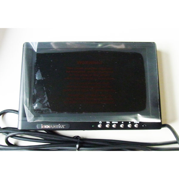 Bought this puppy for 1 JPY on Yahoo auction (ok with 900+ JPY delivery, make it 7 EUR). It's a car TV of the pre-numeric TV era, with a big accompagning box with a lot of inputs outputs, a remote, cables and cables and a 7 inch screen. I was about to write nice but let's face it, it's 10 years old technology with cheapo LCD, so your cell phone screen is waaaaaaaay better. Don't watch bluray here, but for DVD, video game 16bits era or as a small side screen, it's just fine. Oh anyway input is composite of course (NTSC).
 Screen details
It's a 7.8 inches INNOVATIVE model INNOV-780TV, made in Korea. No doc on the internet, even in Japanese, so I safely assume that this will be the only recycling (hacking is a strong word here) guide for this puppy.Car model, so feeds on 12V. It came with a connector box which has 2 (!) TV antenna input (non numeric), 2 Composite (audio+video) inputs, 2 Composite outputs, big fancy cable to connect to screen, and a strange 4 pins power connector. Couldn't find anywhere how to plug that connector, found the ground easily by checking the inside, but the 3 other pins seemed weird for me. Time for plan B.
Screen investigation
Opening the screen, I faced 9 connected pins. By that time I was already 99% sure that somewhere there was one or 2 composite inputs, power (duh), and a few cables to talk from the screen to the connector box (IR remote receptor is on the screen).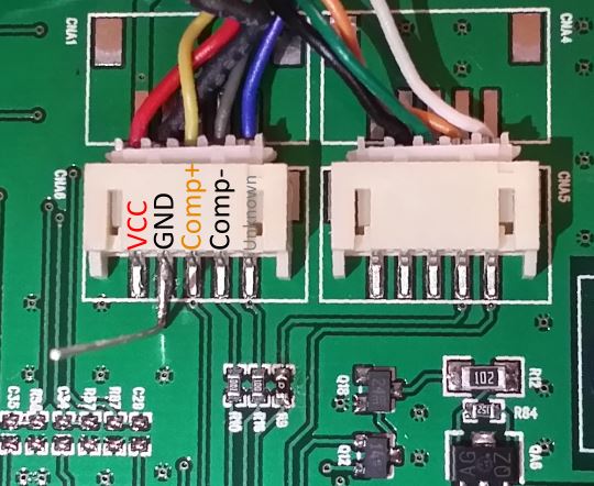
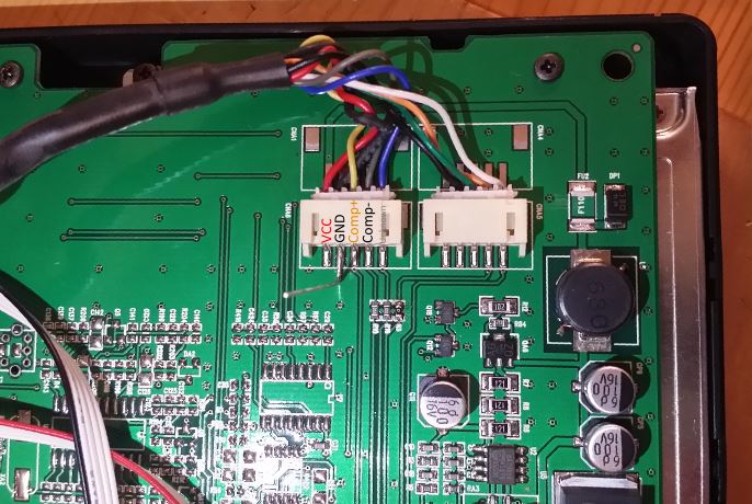
Ok so cable colors, the ground connection and the fact that the red leftmost cable goes to a combo of inductor and voltage regulator, VCC and GND are dad giveaway. It's a car model, so safe to assume it's 12V input. With my Kikusui power generator, I found out that 12V and 750 mA is enough. You can even go down to 8v and 750mA without loosing too much luminosity (at least still useable). Under that voltage the backlight grows deemer and deemer, below what looks like enough to me. Fun thing is a 10V the system uses 1A, though at 8V or 12V 750mA is enough...
Then, it was just a matter of probing here and there where the composite signal goes in. And of course zap yourself with the big inverters (?) for the LCD light background. Conclusion: it is not really fun. Anyway, after covering the dangerous part with tape and probing around, I found them (see the screenshots).
Composite signal generation
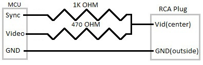
Yes, so to test I need an input composite signal. Don't want to risk to fry my new Raspi3, the Orange Pi is still part a mystery for me, my Wii is downstairs ... Let's use an Arduino! I nearly managed to generate the NTSC signal by myself years ago in the early years of Arduino. Now things changed and one guy made a great library TVout!Lots of thanks to the maker of this libray: it works perfectly, for NTSC too, from the first. 2 resistors and you're in business.
Result
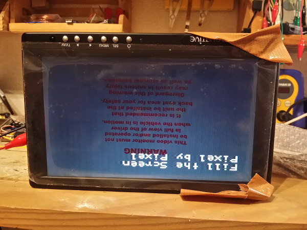
Ok it's upside down, tilt your head. But it's here running the test program of TVout. (^_^)b
electrogeek.tokyo ~ Formerly known as Kalshagar.wikispaces.com and electrogeek.cc (AlanFromJapan [2009 - 2026])